Difference: EnergyCounter (1 vs. 5)
Revision 52015-06-18 - PedroMaiaAlves
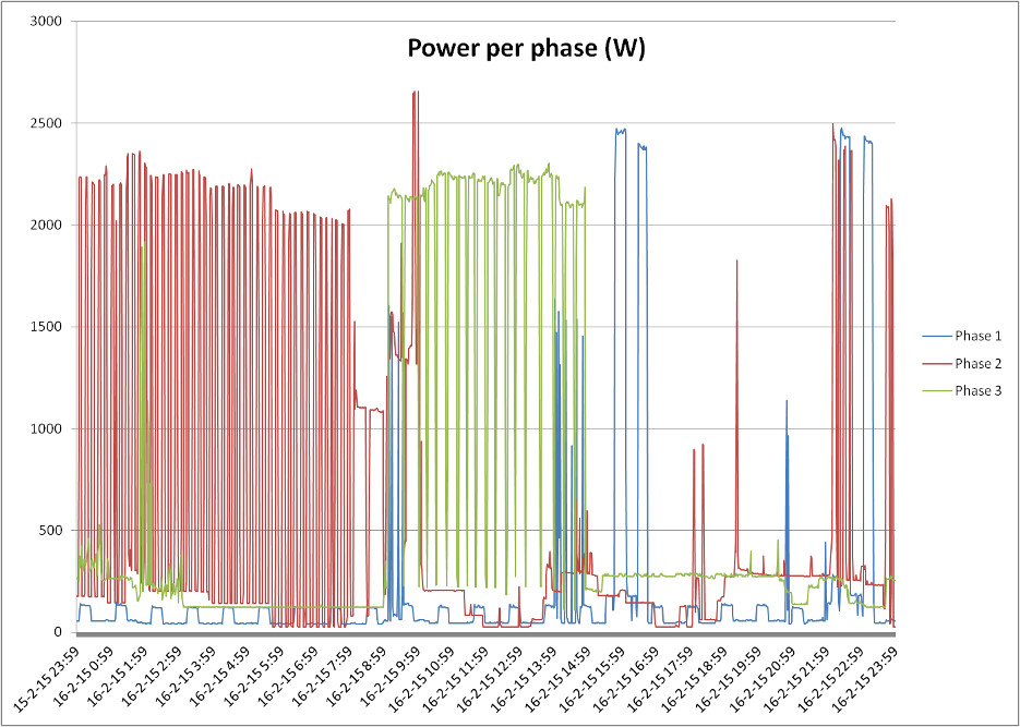
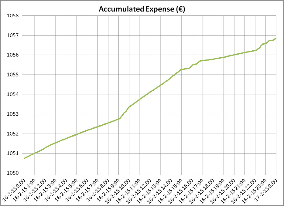 In this day there was an expense of ~€6 and we can see an increase on the rate between 9:00 and 15:00 corresponding to the time where the heater of the living room was turned on.
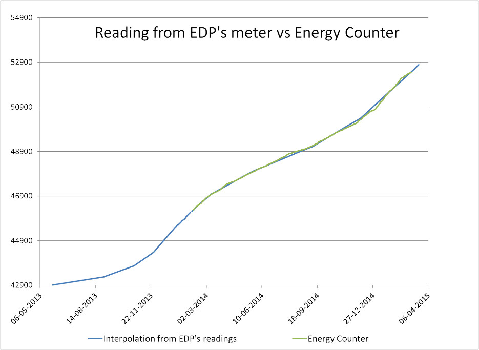
The last picture shows a comparison between the readings on EDP's meter (real or interpolated) in blue and the readings from the Energy Counter in green.
In this day there was an expense of ~€6 and we can see an increase on the rate between 9:00 and 15:00 corresponding to the time where the heater of the living room was turned on.
The last picture shows a comparison between the readings on EDP's meter (real or interpolated) in blue and the readings from the Energy Counter in green.
Revision 42015-06-17 - PedroMaiaAlves
| Line: 1 to 1 | ||||||||
|---|---|---|---|---|---|---|---|---|
Energy Counter Project | ||||||||
| Line: 118 to 118 | ||||||||
Data storage | ||||||||
| Changed: | ||||||||
| < < | ||||||||
| > > | This module doesn't store the data by itself. The objective is to have the data in some place where it can be quickly accessed.
The following figure describes the SW architecture inside the Linux Server. Further detais in the next sub-sections.
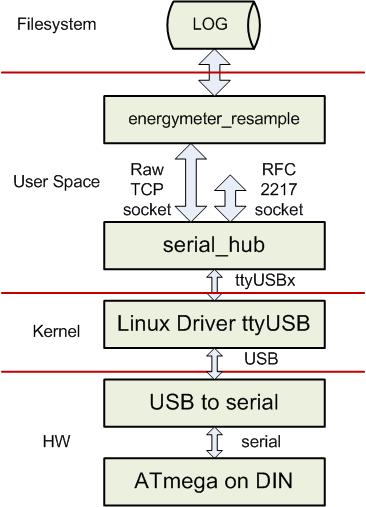
USB to serialThe "USB to serial" adapter is a standard of-the-shelf adapter usually based on a FTDI or Prolific device. In this case the serial interface is done at TTL levels in order to skip all the TTL to/from RS-232 conversion.Linux Driver ttyUSBThe "USB to serial" adapter is directly supported by the Linux Kernel and is mapped into a /dev/ttyUSBxxx device.serial_hubThe serial_hub software, developed by me, has some interesting features, most of them not needed for this specific project. In general:
energymeter_resampleThe energymeter_resample software converts energy consumption events (pulses reported by ATmegaOnDIN) into an average power consumption report once per minute.The output of this SW is something similar to: 1429270680.000000 25.683640 123.180953 182.124549 1429270740.000000 25.680292 123.784811 182.011305 1429270800.000000 25.534447 123.763774 182.006320 1429270860.000000 25.534447 124.544685 181.391650
| |||||||
| Deleted: | ||||||||
| < < | -- PedroMaiaAlves - 2015-06-16 | |||||||
| ||||||||
| Line: 131 to 171 | ||||||||
| ||||||||
| Added: | ||||||||
| > > |
| |||||||
Revision 32015-06-17 - PedroMaiaAlves
| Line: 1 to 1 | ||||||||
|---|---|---|---|---|---|---|---|---|
Energy Counter Project | ||||||||
| Line: 116 to 116 | ||||||||
| ||||||||
| Added: | ||||||||
| > > | Data storage | |||||||
| Added: | ||||||||
| > > | ||||||||
| -- PedroMaiaAlves - 2015-06-16 | ||||||||
Revision 22015-06-16 - PedroMaiaAlves
| Line: 1 to 1 | ||||||||
|---|---|---|---|---|---|---|---|---|
Energy Counter Project | ||||||||
| Line: 89 to 89 | ||||||||
| Some solutions are available to integrate Arduino and other similar boards on DIN rails but they are not compact. | ||||||||
| Changed: | ||||||||
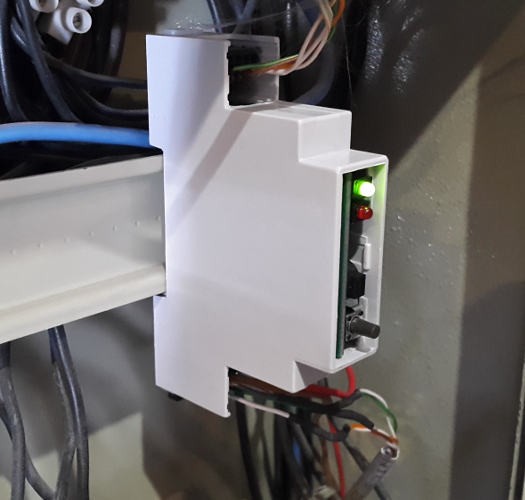
| < < | For this purpose I developed a small board that fits inside a 17.5mm DIN rail module which can be seen on the ATmega on DIN page. | |||||||
| > > | For this purpose I developed a small board that fits inside a 17.5mm DIN rail module which can be seen on the ATmega on DIN page. | |||||||
| This board is powered by 24V, has one LED, one buzzer and one button on it's front plate and has 14 GPIOs and 2 ADC inputs available. In the context of this project, no fundamental difference on the system architecture was need when using the ATmegaOnDIN board. | ||||||||
| Line: 113 to 113 | ||||||||
| ||||||||
| Changed: | ||||||||
| < < |
| |||||||
| > > |
| |||||||
| ||||||||
Revision 12015-06-16 - PedroMaiaAlves
| Line: 1 to 1 | |||||||||||||||||||||
|---|---|---|---|---|---|---|---|---|---|---|---|---|---|---|---|---|---|---|---|---|---|
| Added: | |||||||||||||||||||||
| > > |
Energy Counter ProjectEverything started with the idea of measuring the energy consumption of my house mainly due to some huge electricity bill that arrived to my mailbox... My solution for the problem is based on three components:
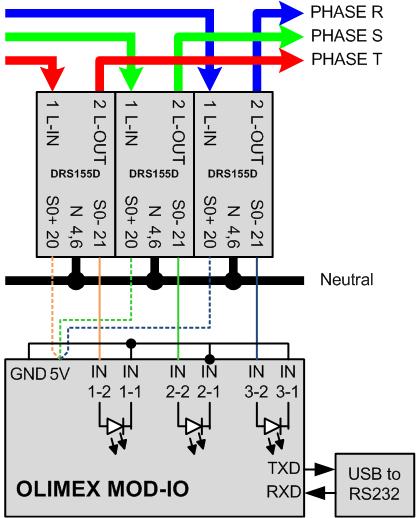
Energy MeterMy house has a three-phase supply and I need to measure the energy consumption on each phase independently. For my project I've used 3 x DRS155DC which I've found here http://bg-etech.de/os/product_info.php/products_id/40 but was acquired through amazon.de.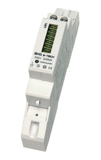 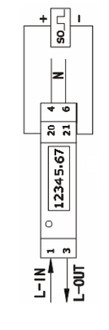 In this module the input phase is connected on connection 1 and the output phase is connected on connection 2.
The neutral is connected on connections 4 and 6.
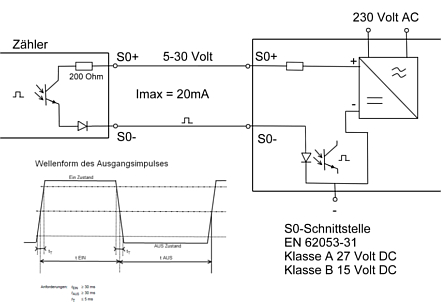
The energy measurement is done on connections 20 and 21 (in an upper level) which implements a DIN EN 62053-31 interface AKA S0-Schnittstelle.
In this interface, every time 1Wh is measured by the energy counter, one pulse with a few milliseconds (>30ms) is generated.
In this module the input phase is connected on connection 1 and the output phase is connected on connection 2.
The neutral is connected on connections 4 and 6.
The energy measurement is done on connections 20 and 21 (in an upper level) which implements a DIN EN 62053-31 interface AKA S0-Schnittstelle.
In this interface, every time 1Wh is measured by the energy counter, one pulse with a few milliseconds (>30ms) is generated.
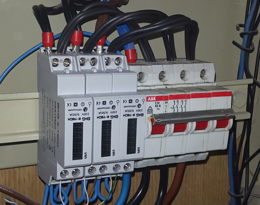
 The three energy counters were installed on the electrical box close to the main power breaker.
 These pulses must be captured in real-time.
Real-time data captureEach one of the three-phase meters will generate one pulse every time 1Wh is measured. These pulses must be counted and recorded.On my house I have a linux "server" (EEE Box PC) which is used to record the energy consumption but can't, of course, directly capture the pulses from the energy meters. To capture the real-time data I've use an ATmega system in two steps. Step 1 - Olimex MOD-IOIn order to prototype the real-time data capture I've used and MOD-IO from OLIMEX.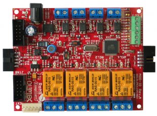 The MOD-IO board has a lot of features but the most relevant for this application are:
 The software doesn't receive anything through the serial interface and its output is something similar to:
K 0095714786
2 0095715022 0000001986 0000039514
K 0095715272
1 0095715447 0000002887 0000049680
0 0095715565 0000014099 0000050803
K 0095715815
K 0095716065
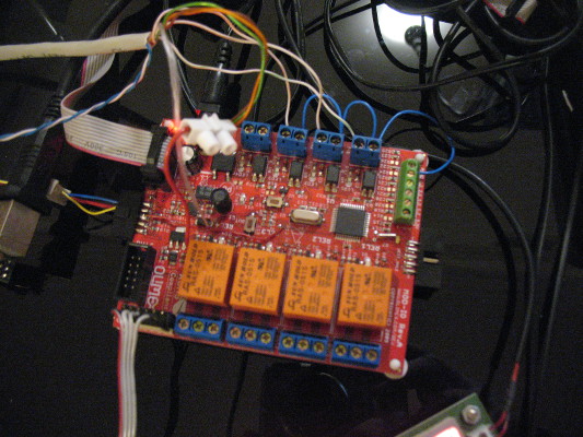
Step 2 - ATmega on DIN railAfter the prototyping with OLIMEX's MOD-IO this project needed some professional touch. The ATmega board must be placed directly on the electrical box just like any other standard DIN rail module, side-by-side to the breakers. Some brief search on the Internet didn't show anything as simple as what I need for this project. My requirements were very basic:
This board is powered by 24V, has one LED, one buzzer and one button on it's front plate and has 14 GPIOs and 2 ADC inputs available. In the context of this project, no fundamental difference on the system architecture was need when using the ATmegaOnDIN board. 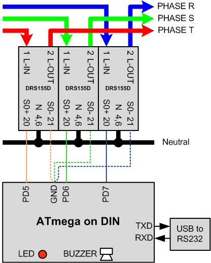 The differences are:
| ||||||||||||||||||||
View topic | History: r5 < r4 < r3 < r2 | More topic actions...
Ideas, requests, problems regarding TWiki? Send feedback