Energy Counter Project
Everything started with the idea of measuring the energy consumption of my house mainly due to some huge electricity bill that arrived to my mailbox... My solution for the problem is based on three components:- Energy Meter
- Real-time data capture
- Data storage
Energy Meter
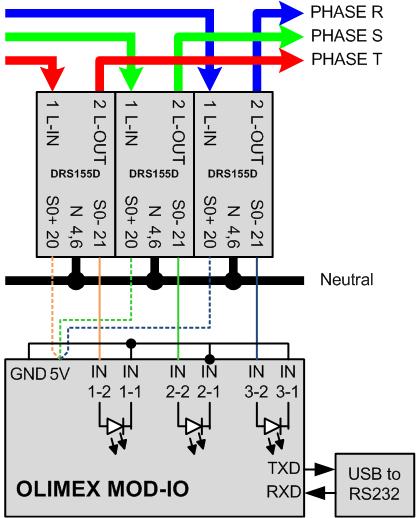
My house has a three-phase supply and I need to measure the energy consumption on each phase independently. For my project I've used 3 x DRS155DC which I've found here http://bg-etech.de/os/product_info.php/products_id/40 but was acquired through amazon.de.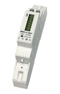
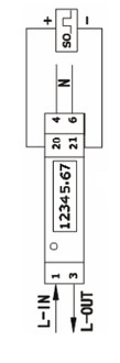 In this module the input phase is connected on connection 1 and the output phase is connected on connection 2.
The neutral is connected on connections 4 and 6.
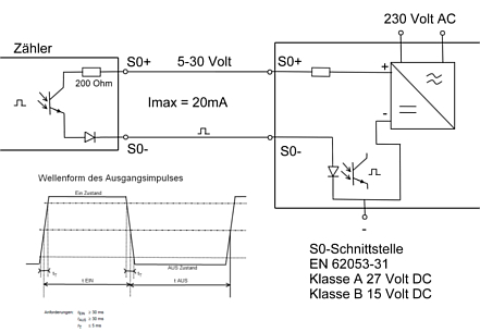
The energy measurement is done on connections 20 and 21 (in an upper level) which implements a DIN EN 62053-31 interface AKA S0-Schnittstelle.
In this interface, every time 1Wh is measured by the energy counter, one pulse with a few milliseconds (>30ms) is generated.
In this module the input phase is connected on connection 1 and the output phase is connected on connection 2.
The neutral is connected on connections 4 and 6.
The energy measurement is done on connections 20 and 21 (in an upper level) which implements a DIN EN 62053-31 interface AKA S0-Schnittstelle.
In this interface, every time 1Wh is measured by the energy counter, one pulse with a few milliseconds (>30ms) is generated.
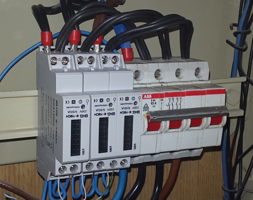
 The three energy counters were installed on the electrical box close to the main power breaker.
 These pulses must be captured in real-time.
Real-time data capture
Each one of the three-phase meters will generate one pulse every time 1Wh is measured. These pulses must be counted and recorded.On my house I have a linux "server" (EEE Box PC) which is used to record the energy consumption but can't, of course, directly capture the pulses from the energy meters. To capture the real-time data I've use an ATmega system in two steps.
Step 1 - Olimex MOD-IO
In order to prototype the real-time data capture I've used and MOD-IO from OLIMEX.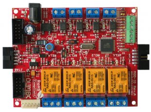 The MOD-IO board has a lot of features but the most relevant for this application are:
 - Open source hardware board with ATMega16L-8AU microcontroller
- 4-optocoupler isolated inputs with screw terminals
- Input status LEDs
 The software doesn't receive anything through the serial interface and its output is something similar to:
K 0095714786
2 0095715022 0000001986 0000039514
K 0095715272
1 0095715447 0000002887 0000049680
0 0095715565 0000014099 0000050803
K 0095715815
K 0095716065
- The first field reports in which "phase" an additional 1Wh was measured.
- 0,1 or 2 - Phase number
- K - Keep-alive sent after 2.5 seconds without measured consumption
- The second field reports how much time has elapsed since the MOD-IO startup (in 1/100th of second) - 0095715022 means 11 days 1 hour 52 minutes 30.22 seconds
- The third field reports how much time has elapsed since the last pulse - deltaT. Can be used to compute the average power = 360000 / (deltaT) in W - 1986 means 181.3W
- The forth field reports how many pulses were already counted since MOD-IO startup
Step 2 - ATmega on DIN rail
After the prototyping with OLIMEX's MOD-IO this project needed some professional touch. The ATmega board must be placed directly on the electrical box just like any other standard DIN rail module, side-by-side to the breakers. Some brief search on the Internet didn't show anything as simple as what I need for this project. My requirements were very basic:- Micro-controller based board
- A solution as compact as possible (width equivalent to a power breaker would be interesting)
- Direct access to the micro-controller GPIOs
- Optional - Buzzer to warn on excessive power
- Optional - LED to signal each 1Wh measured
- Powered by 24V (available from my domotics system)
This board is powered by 24V, has one LED, one buzzer and one button on it's front plate and has 14 GPIOs and 2 ADC inputs available. In the context of this project, no fundamental difference on the system architecture was need when using the ATmegaOnDIN board.
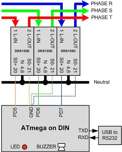 The differences are:
 - Pulses from energy meters pull the input low - Pull-up needs to be enabled on ATmega inputs
- The LED pulses once for each energy counter measurement pulse
- The buzzer beeps when the power on, at least, one phase exceeds a predefined limit.
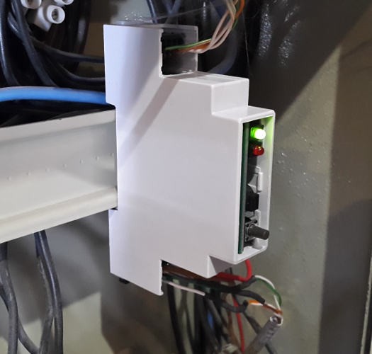
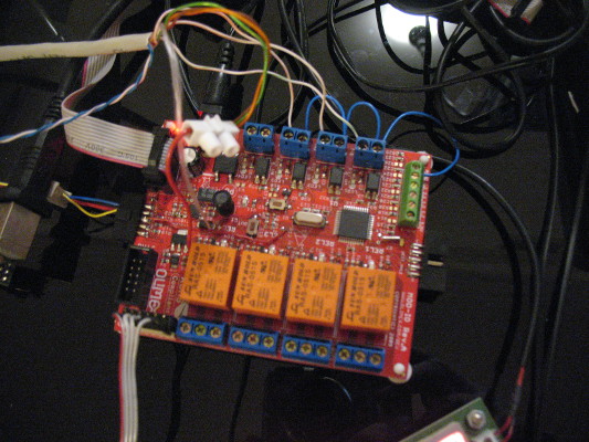
- On the top side it's possible to see the connections going to the energy meters.
- On the bottom, the UTP cable is connected to an USB to serial (TTL) adaptor
- The red and the brown wires are connected to the 24V power distribution
- On the front plate:
- The green LED is on when internal power is available
- The red LED pulses according to energy measurements
- The buzzer (just above the push-button) to warn on excessive consumption
- The push-button is not used in this application
Data storage
Topic revision: r3 - 2015-06-17 - PedroMaiaAlves

|
|
|
|
Ideas, requests, problems regarding TWiki? Send feedback